Motorized Zipline
- CategoryFor fun
- Project dateAugust 2025
- Skills used3D printing, CAD, FEA, carpentry
About this
This project was part of the Formlabs Hackathon, a weekend-long event where Formlabs employees focus on building cool stuff. Our team collaborated with one of the visiting content creators, Quint from Quint BUILDs. During the weekend, we printed and built all the hardware, which Quint then took for testing at his family's house.
On our team, I was responsible for:
- CAD of the trolley and mechanical integration of electronics
- Construction of a temporary zipline setup on the loading dock of Formlabs HQ
When we were first ideating, we decided we had a couple goals:
- The zipline should ensure rider safety as much as possible and therefore should not suddenly accelerate or decelerate
- The zipline should auto-return itself back up to the top at the end of the ride
- The entire trolley (minus electronics) should be 3D printed - we decided that welding a trolley would be too easy!
.png)
.png)
.png)
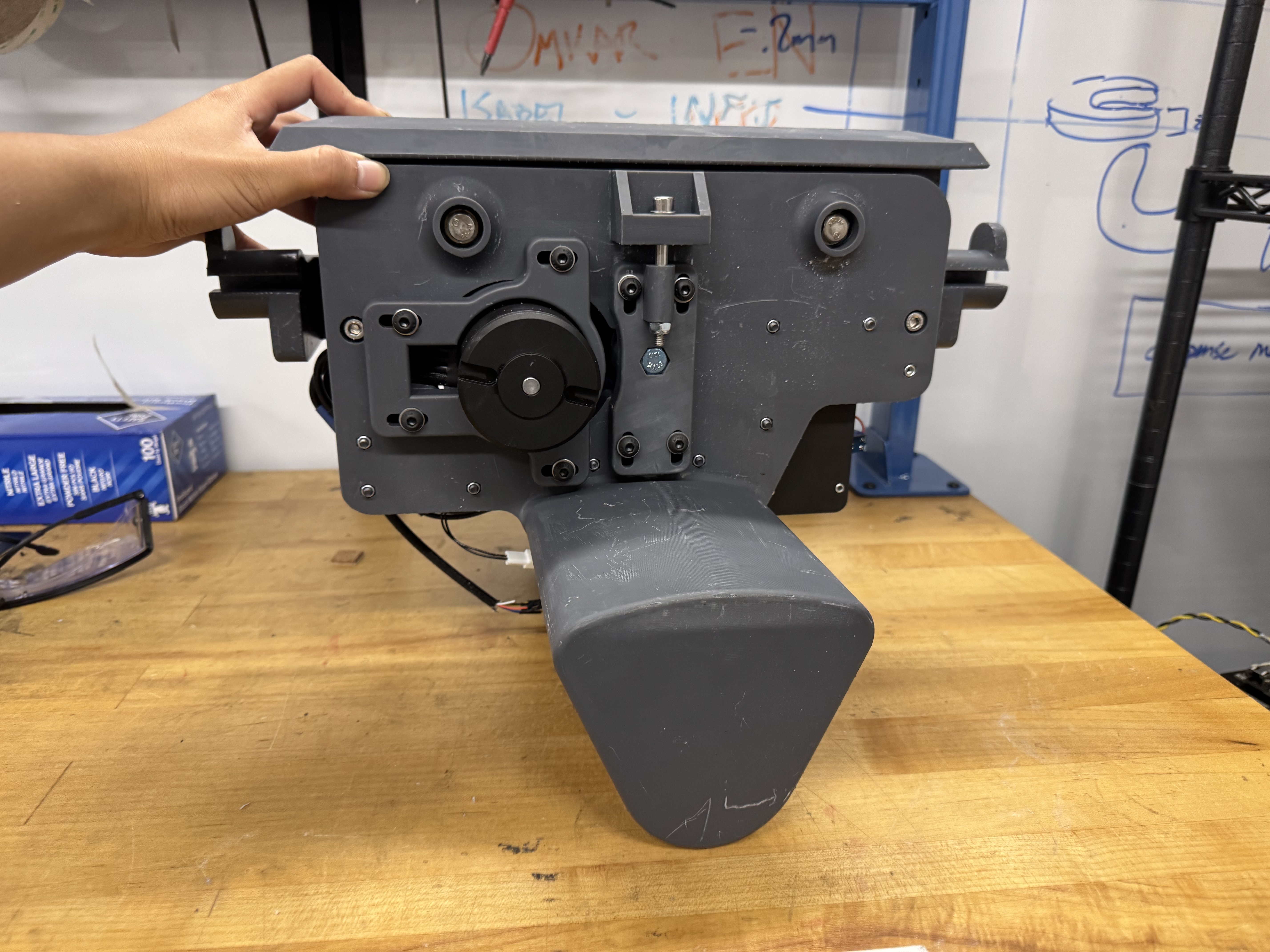
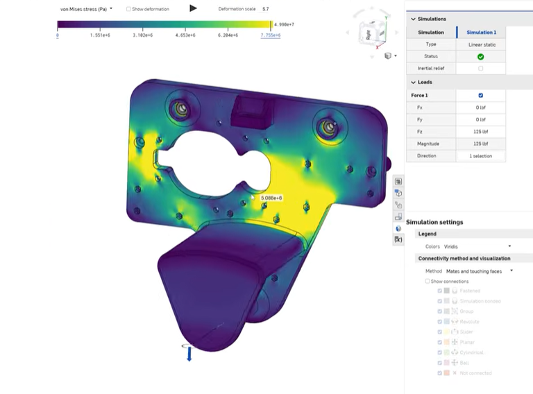
Trolley Design
To make sure the trolley was safe to handle the load of a person, we did FEA simulating the loading conditions using the materials spec sheet for Tough 2K resin and found we were well within a x10 safety factor. There are other design considerations for 3D printed parts like brittle fracture and weakening due to UV exposure, but we weren't too worried about that for such a short hackathon.
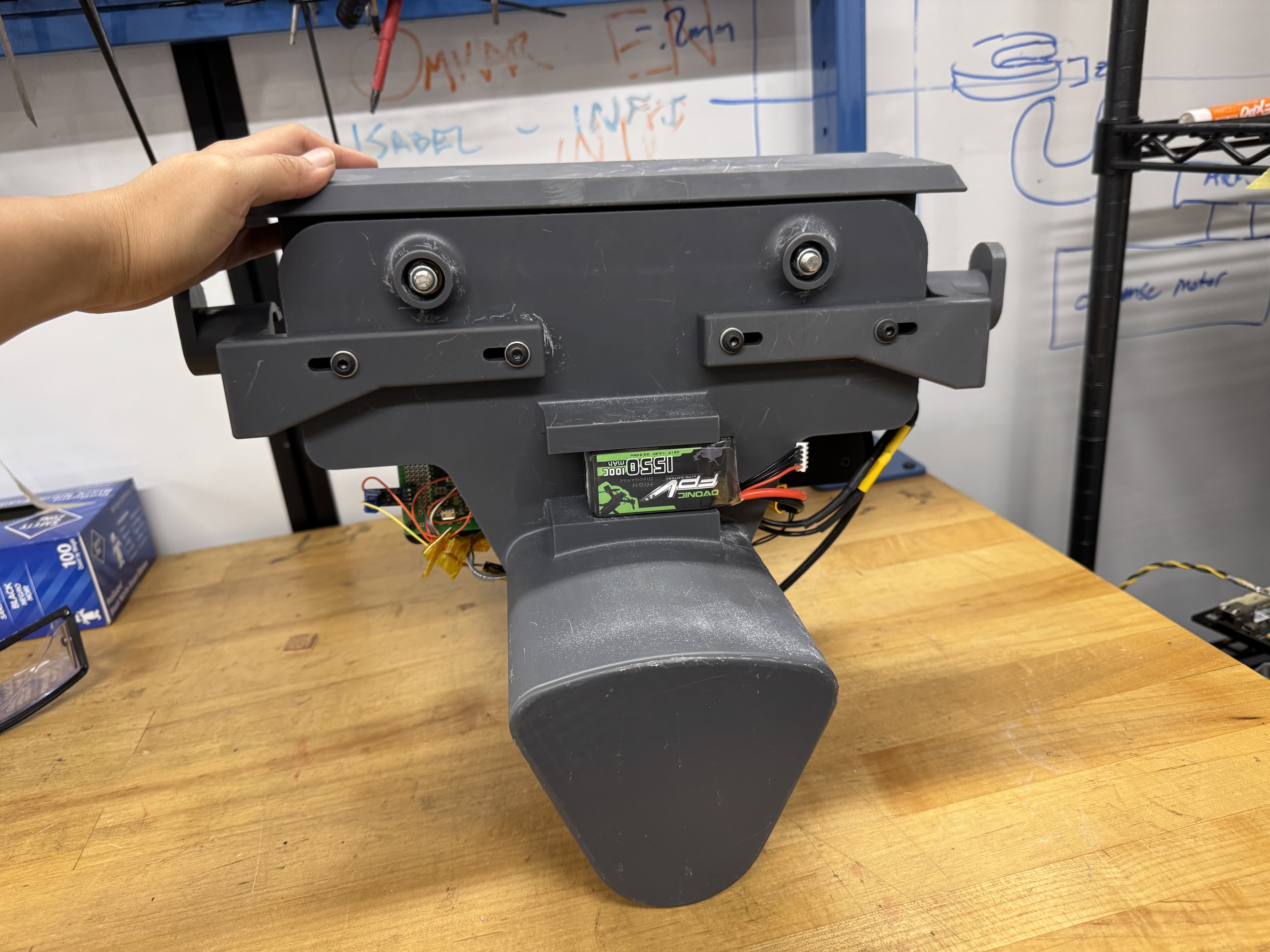
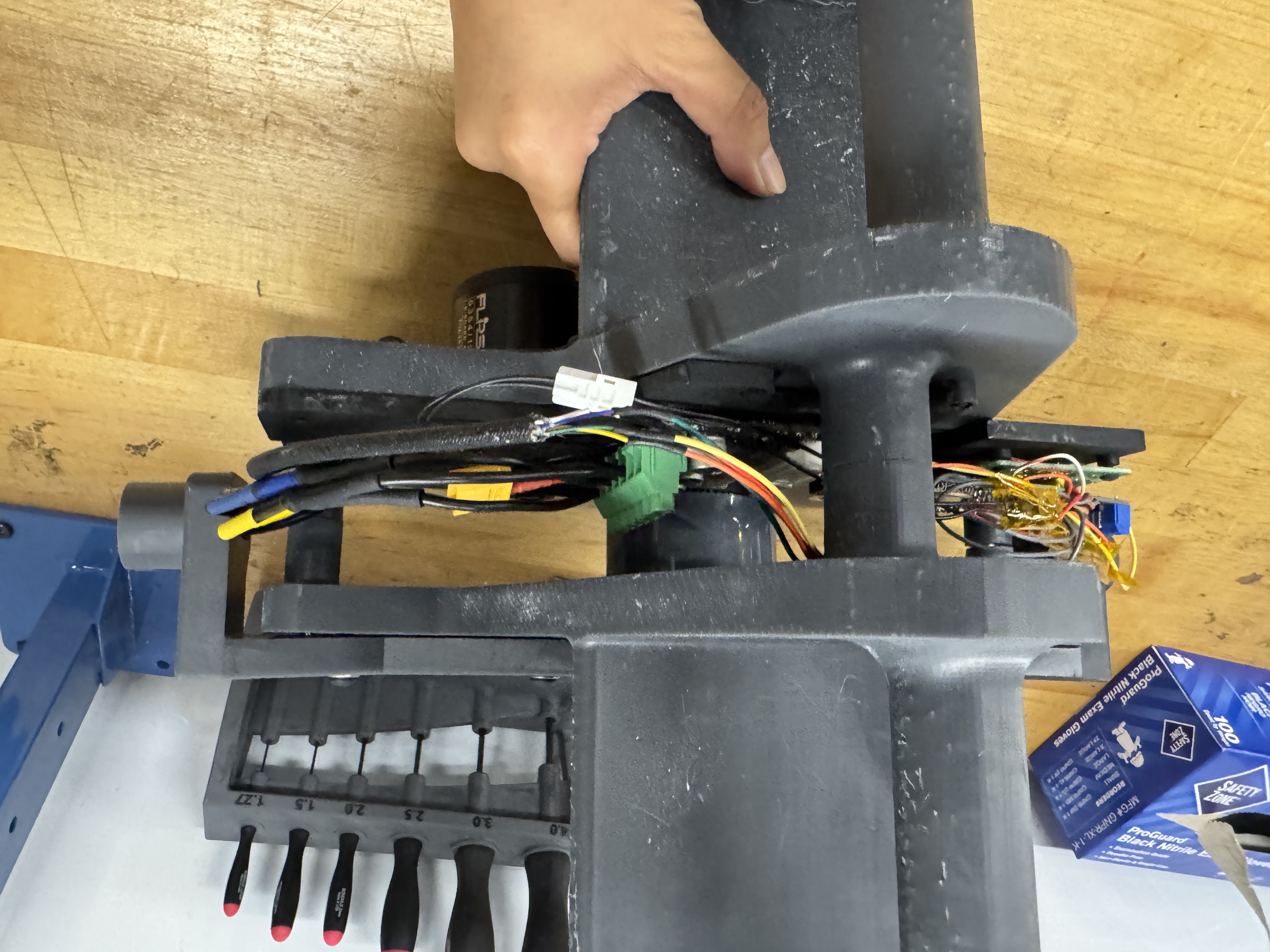
After SLA printing all the parts in Tough 2K resin, I press-fit the bushings in and assembled the trolley. Because our electronics still hadn't come in by the time we had done the main trolley's CAD, I added generic mounting holes to the trolley so that we could add in the electronics mounting later on.
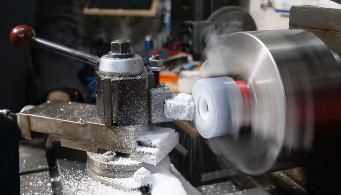
To drive the trolley, we used an ODrive Pro motor controller, a motor, and a skateboard wheel driven by a timing pulley. To get the skateboard wheel to fit, we had to turn it down on the lathe. We had the timing pulley on slots so that you could adjust the tension. The "brains" of the system was an ESP with a WiFi module so we could remotely operate it if need be.
At the end of each side of the trolley, I added a bumper so that if the trolley made a hard collision with the end stop, that would break first.
Zipline Setup
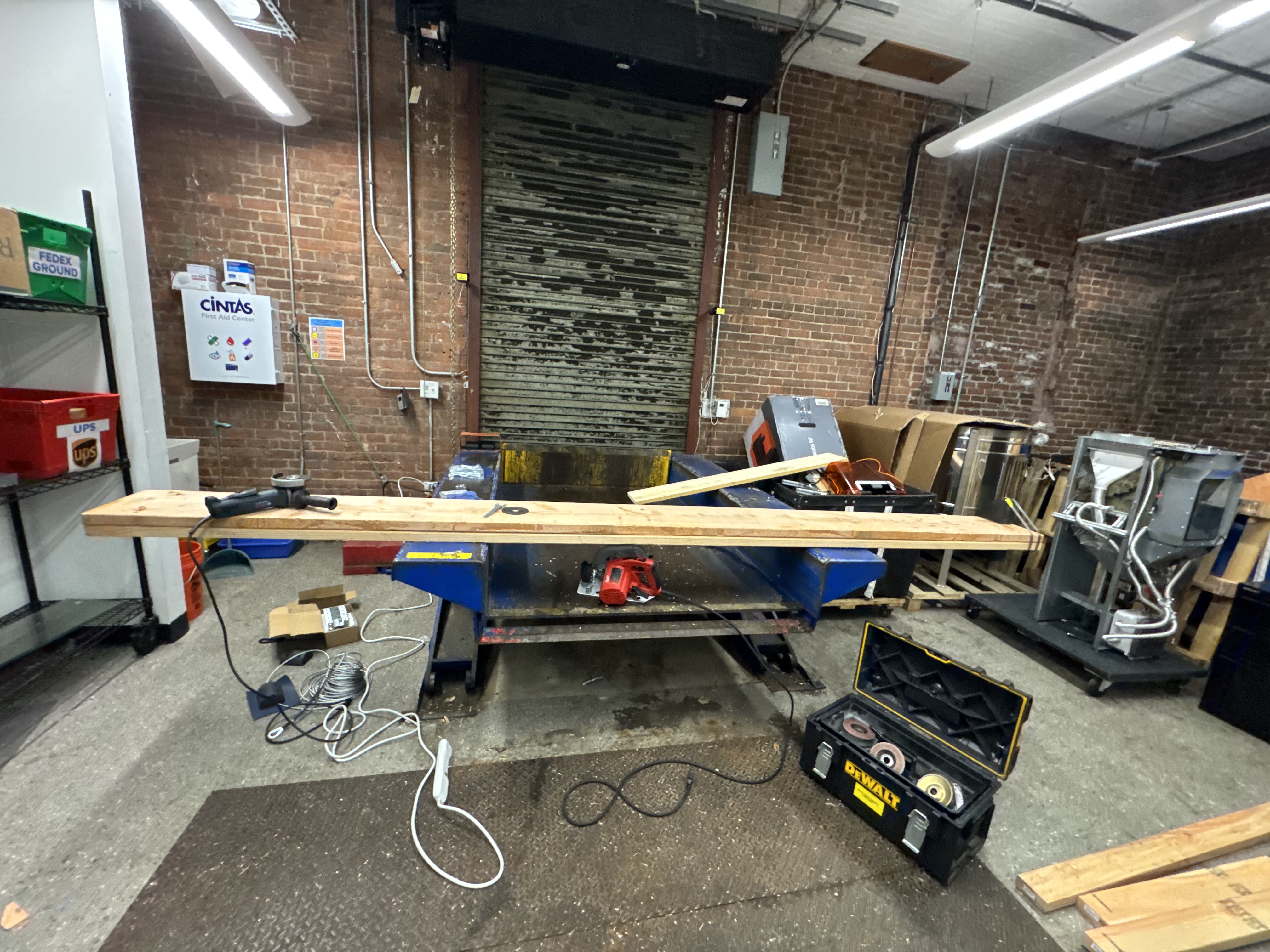
Setting up the zipline was tricky, since it needed to be temporary for just the weekend so the loading dock could operate as normal on Monday. That meant, unlike typical zipline installs, we couldn't sink the post into concrete to secure it.
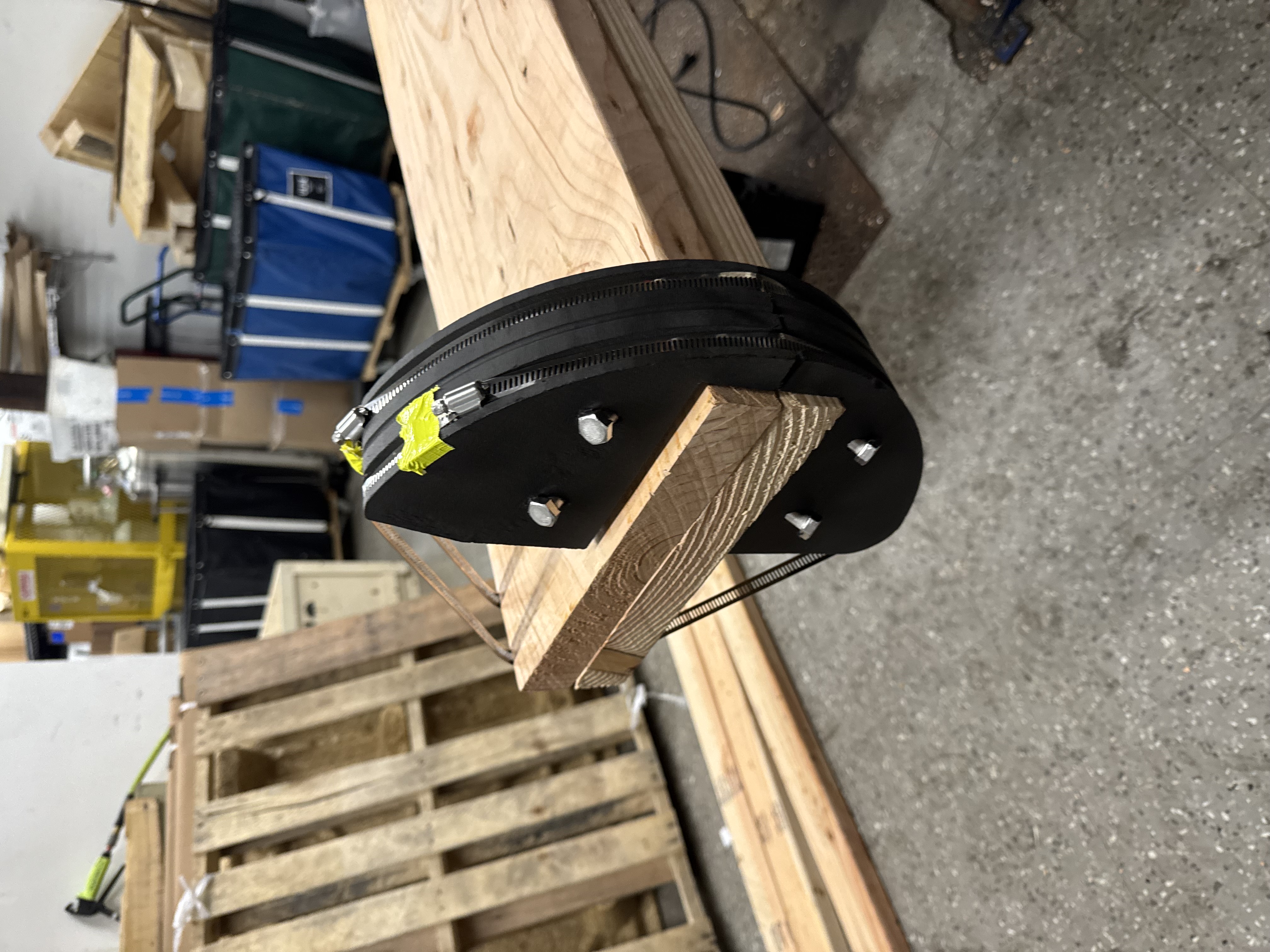
We first got a ton of 2x4s and 2x10s at Home Depot. I used lag bolts to combine the 2x10s side by side, angle grinding off any sharp bits that could cut people. To prevent the cable from slipping down the post or creasing in the corners of the post, I printed a semicircular support, which I lag bolted and hose clamped onto the post so it was secure. To secure the posts upright, I used several 2x4s as trusses, which I lag bolted directly into the dock.
Finally, I ran the steel cable from the upper post to the shorter one, tensioning it just enough that the ride was fun but not fast enough that you would hurt yourself on the landing.
To create hard stops on each side of the zipline, I designed and printed cylindrical end stops. I SLS printed them and used heated inserts to add threads. Then I screwed the two pieces together with the cable sandwiched in the middle.
.jpg)
.jpg)
.jpg)
Software
We used the IMU to determine which direction and speed to run the motor. At the start of the ride, you give the trolley a slight tug forwards to indicate you want to ride. This releases the brake and sets the motor to drive mode, which drives you down the zipline. We had this on a slow setting for safety reasons at the hackathon, but Quint really pushes it to its limits in his video. At the end of the ride after you disembark, you tug the trolley towards the top, indicating to the trolley to drive itself back up to the top. Once the trolley hits the hard stop at the top, it holds its position and awaits input to start the next ride.