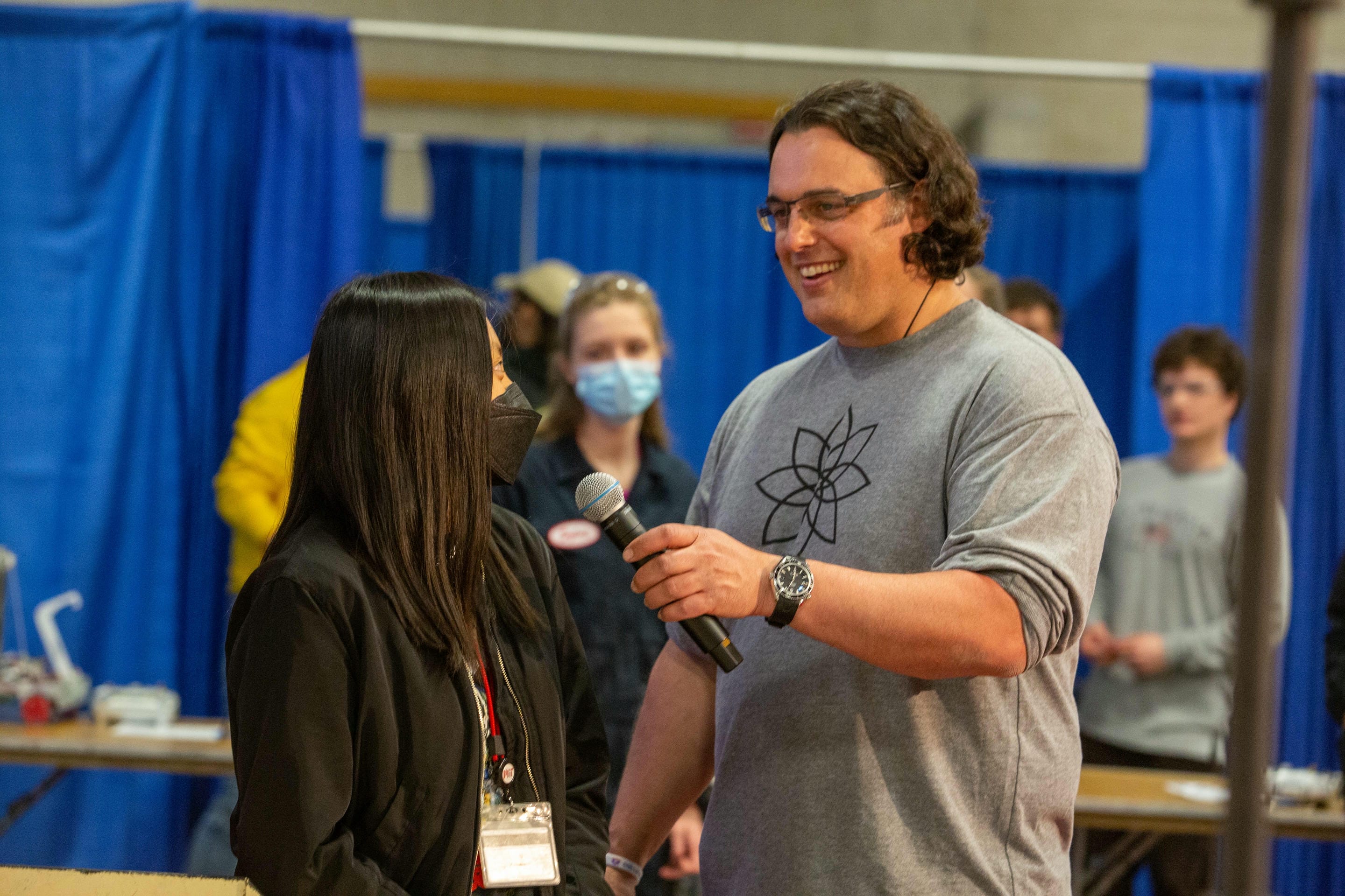
Competition robot
- CategoryClass project
- Project dateSpring 2022
- Skills usedDesign, manufacturing, machining (mill, drill press, lathe, CNC, waterjet, laser cutter, brake), CAD
About this project
For 2.007, Design and Manufacturing I, students are tasked with building a 12”x12”x16” robot capable of scoring as many points as possible on a game board. All components are machined by students from raw stock of aluminum and delrin, teaching students skills such as turning on a lathe, milling, tapping, circuits, and drill pressing.
The robot is driven by two speed servos in continuous mode. When plugged into an RC communicator, these can be remotely controlled via skid steering.
To ensure a tight turn radius for maneuverability, I turned two delrin nubs on the lathe. Unlike wheels, which skid around, these nubs would scoot along the floor of the game board with low friction, enabling the robot to turn in place.
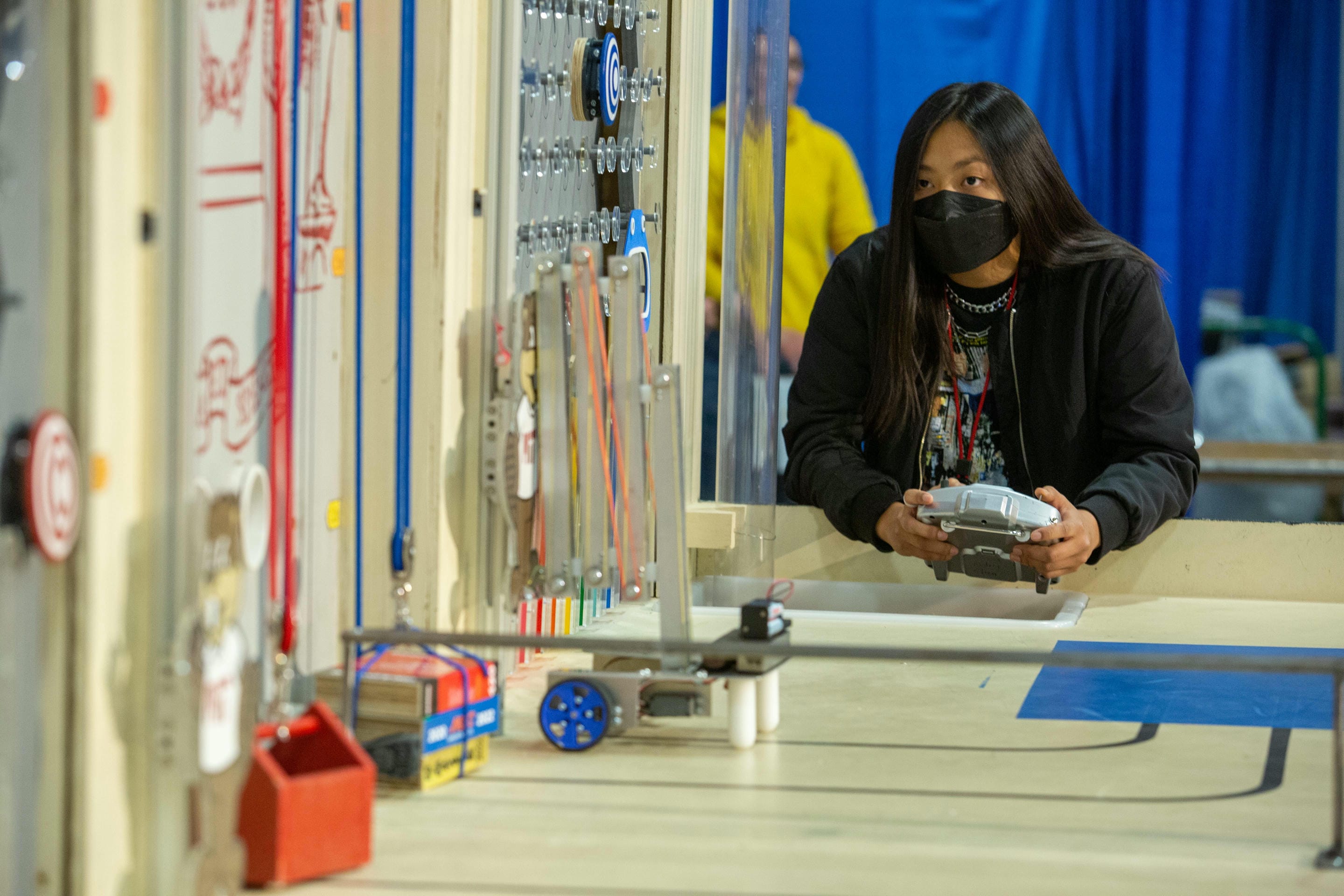
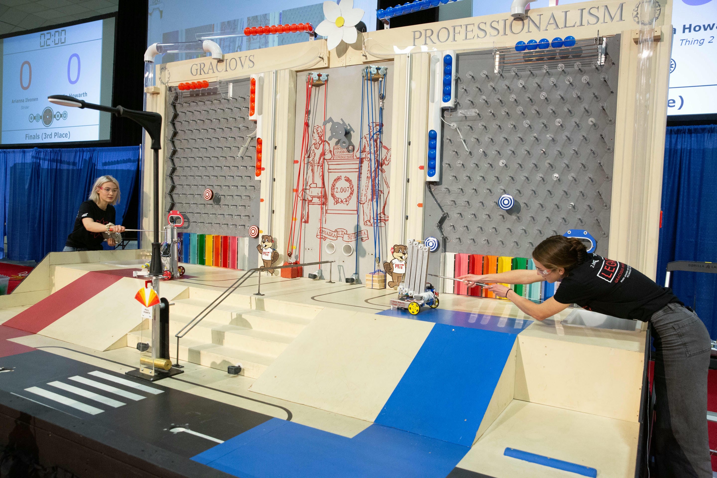
The competition game board had several different tasks for your robot to attempt. Two robots would compete side by side simultaneously on their half of the board. The robot can start anywhere on the gameboard, but because tasks are at different levels, it might be necessary to climb or descend the ramp to access all the tasks. There is also an element of randomness to scoring as well, since hitting the buttons drops balls into the pachinko board, and depending on which color pocket it rolls into, you'll get a different number of points. As you might expect, your robot isn't allowed to harm the other robot.
Each round would end after 2.5 minutes, then points would be totaled. There were many different tasks to attempt, but after doing some calculations to optimize my point total in a given timeframe, I decided I wanted my robot to be able to push both buttons, lift Tim the beaver to the top, and rotate the lamppost.
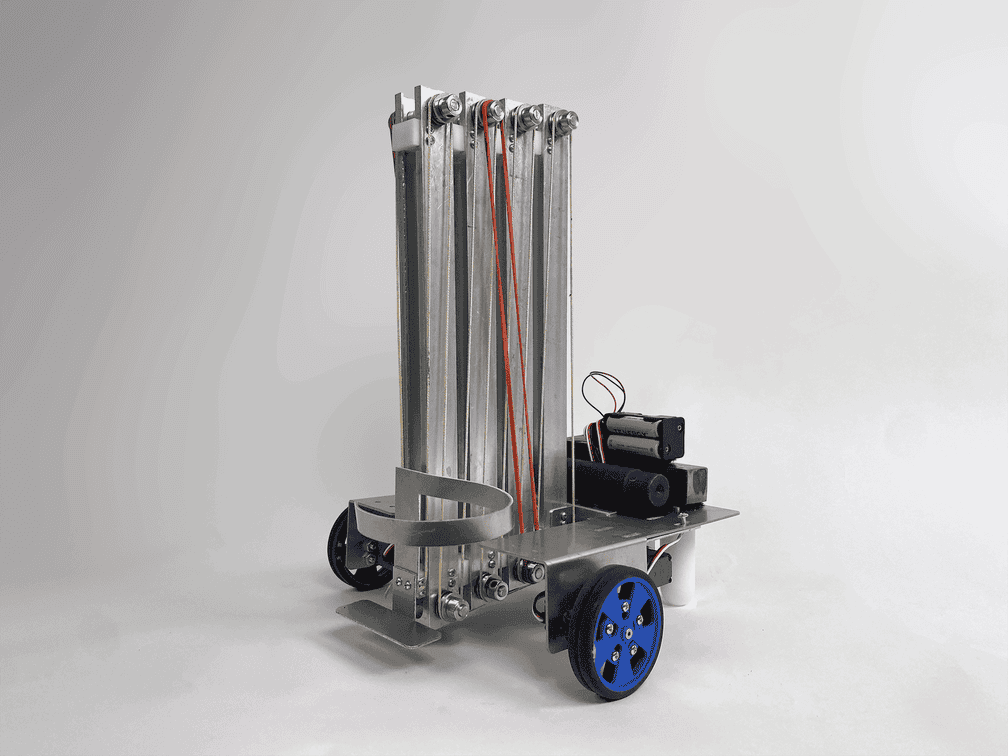
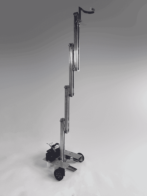
My biggest module was a linear sliding lift. I needed this vertical lift in order to lift up Tim the beaver, press both the upper and lower buttons, and pull down the lamppost. For my first prototype of this module, I developed a belt system linking several linear slides. These slides were produced by cutting slots into box aluminum, and fitting milled delrin sliders inside the slots. The delrin had tapped holes which allowed me to mount the delrin to one of the aluminum bars, while allowing the other bar to slide by freely. Deburring the aluminum sliders and testing tolerances were key in this design process to get the prototype sliding properly. This was my first time machining for a larger project, and I had a great time with it, working long nights in shop.
Though this system was very fast at lifting, I eventually changed my design due to issues skipping on the timing pulleys despite my efforts to tension the belts. My new design, however, took advantage of the majority of the parts I had machines for the slides themselves.
My new lift design was a continuous lift using strings attached to a winch. As the winch was wound by a high torque motor, the string would shorten, raising the lift. Using the speed-torque curves for each available motor, I was able to maximize the speed at which the heavy beaver could be lifted, which was important since additional points were granted for accomplishing tasks first and the rounds were only 2.5 minutes long. Then, after lifting the beaver, I'd move on to push the buttons using the same lift.
In order to tip over the lamppost, I needed to design something which could grab onto it and torque it downwards. After some testing, I found the robot was unable to push the lamppost from the bottom since the motors driving the robot couldn't push hard enough. So instead, I thought I'd make use of the lift once again; by hooking the lamppost at the top and pulling from there, the robot would not need to pull with as much force to supply the same torque since the distance between the applied force and the pivot point was higher. Thus, the same module could be adapted for this new task with the addition of a hook, which was carefully designed to be out of the way of the beaver when lifting.
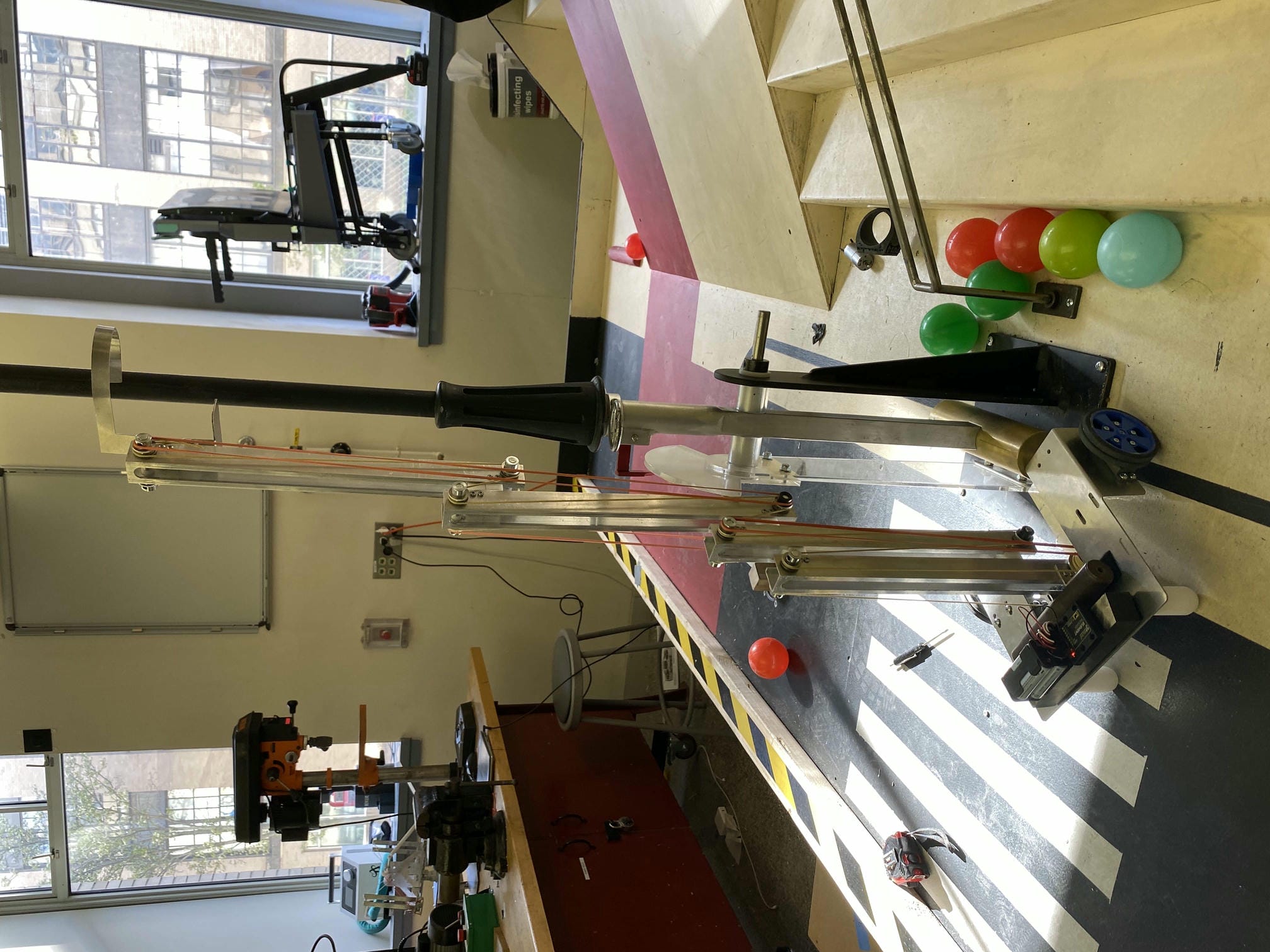
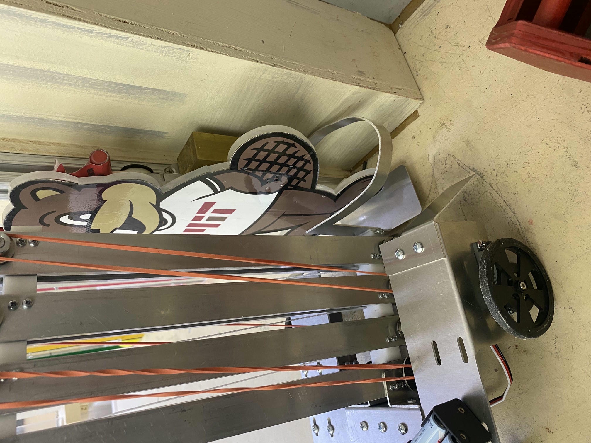

My lift was now able to go up consistently, but it would get stuck at the top because of friction even when the string was given slack. Keeping it extended was not an option, since I wanted to do the beaver lift first to maximize the number of points I got, but then subsequent tasks would require the lift to be lowered. Namely, both the upper and lower buttons were below the top height of the beaver lift, and if I tried to go down the ramp with the lift fully extended, the robot would tip over. In order to fix this, I attached rubber bands between each set of slides. The rubber bands would pull each slider towards one another, getting rid of any slack in the string and compressing the lift. That way, when the servos were spun the other way, the string would be tensioned and the lift would lower. Through some testing, I found that it was best to alternate which side the rubber bands was on because otherwise, it would pinch the sliders towards one another either to the left or right and cause them to catch.
In order to support the lift, I created a baseplate below the main chassis of my vehicle. This way, instead of having the lift just sit on top of the robot, it sits below it on a plate in-between the wheels. This lowers the center of mass of the vehicle, which would improve stability on turn and prevent tipping on the ramp.
Nonetheless, because the lift is inherently top-heavy, I found it was necessary to add fins to the base of the robot to act as a “foot” when climbing the ramp. This extended overall footprint of the robot, which prevented it from tipping backwards. If you're curious about the math behind this, feel to take a look at my calculations here.
Here is a video of the robot climbing a demo ramp I set up without tipping or slipping thanks to the fins.
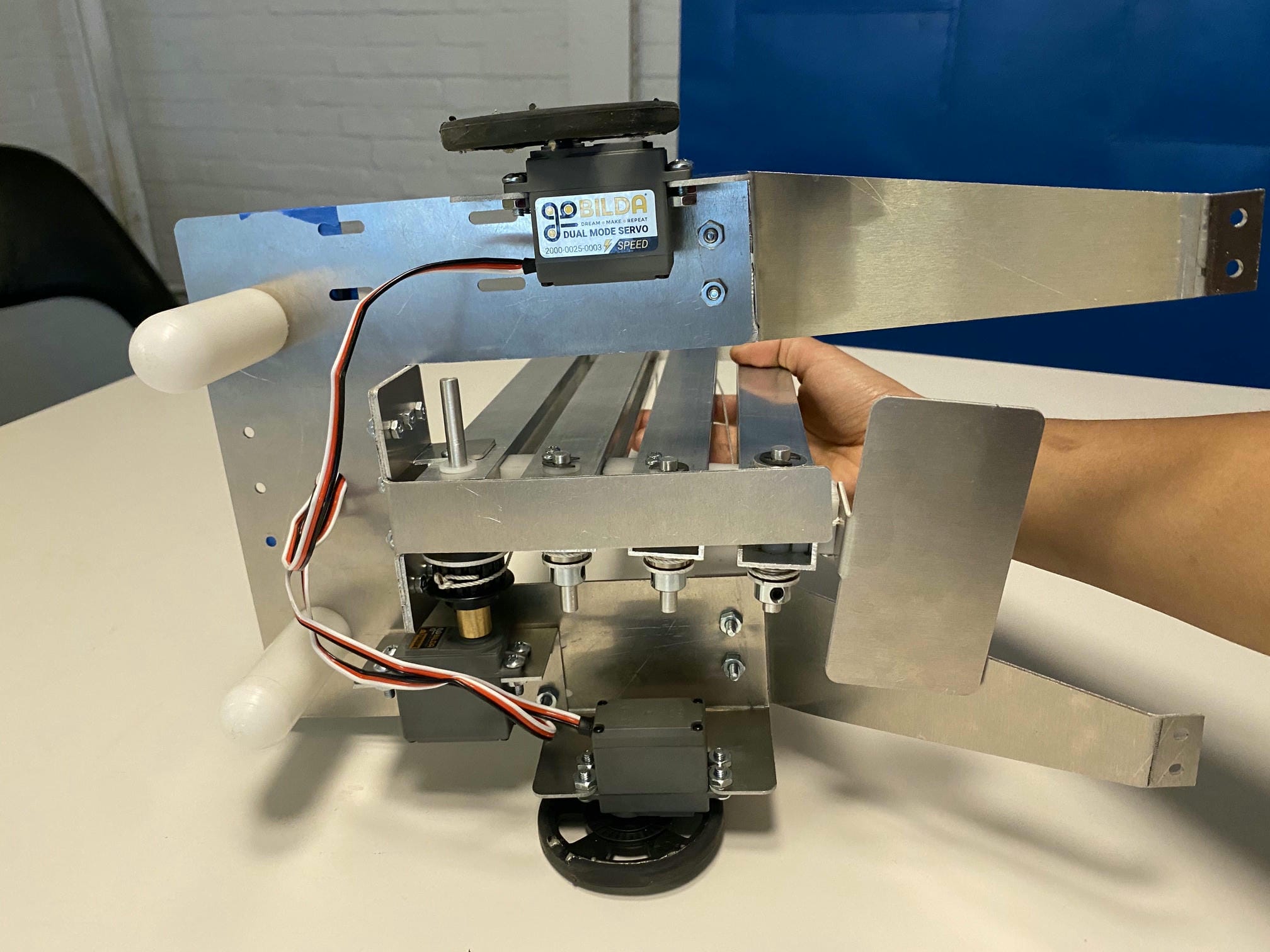
Ultimately, I advanced to the semifinals round and placed in the top 10% of robots. I really enjoyed machining my robot (even though it was incredibly laborious work). This was a very comprehensive experience in the design process, with near constant prototyping, which I found to be a very fun hands-on application of my learning.
